Riyas P.K-Fab Academy 2016
Computer Aided Design
The assigngment for this week was to model (draw, render, animate, simulate, ...) a possible final project, and post it on our class page. The goal was to try, but not necessarily master, as many different software packages as possible so that we have a better understanding of the available alternatives. I installed and tested a wide range of software packages for Windows and Ubuntu. Some of the software was free and open-source while others were demo versions of high-end expensive commercial packages.
2D, 2.5D Design Softwares
This includes Raster graphic programs and Vector based graphic programs.These are designed to simulate drawing with pencils, paint brushes, etc.I tried the Ubuntu versions of GIMP and Inkscape.Both of them can be found on ubuntu software center and available in Windows and Mac OS.The first was recommended to sketch drawings, the second to describe them in a better way adding parameter and hierarchy. One more important feature is the capability of describing relation, this will be fundamental when designing modular structure to be fabricated with 2D cutting machines.
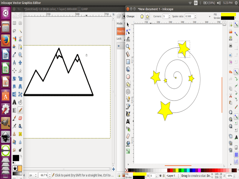
Trying out Gimp and Inkscape.
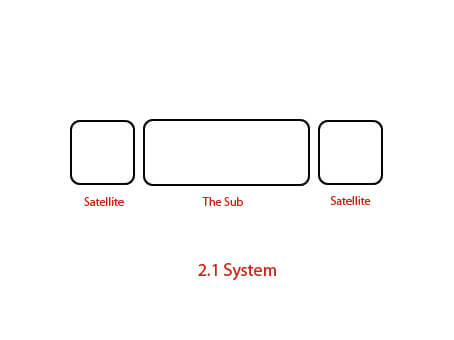
Then,I used Adobe Photoshop(windows version) to create a 2D sketch of my project.In this I used shape tool to create the rectangles and type tool for writings.Like every one else I have previous experience in photoshop.In my opinion it is the most powerful image editor which has a simple learning curve.
3D CAD Software
Using 3D software is complicated by the fact that most pointing devices and displays only work in two dimensions. 3D software is also more complicated because of the addition of the third dimension. Usually using 3D software involves lots of terminology like curve, surface, mesh, planes, NURBS, and primitives. In some software, you can draw using 3D shapes and use Boolean operations to make more complex shapes. For example if your design calls for drilling a hole in a block, you could draw a solid 3D box object and remove a cylinder object from it using a Boolean subtract operation. Another approach is to "sketch" in 2D and then extrude, pad, etc. a third dimension to make it a 3D object.
I tried windows version of Blender.Blender work differently than most engineering CAD software. Blender-like apps are focused on manipulating the textures, colors, and other attributes of surfaces. However, those apps lack the ability to easily specify specific dimensions that you need to manufacture a part, as well as the ability to generate engineering drawings a machinist needs.Blender is an artistic tool, it is not intended for precision.I followed a tutorial in youtube to learn blender.
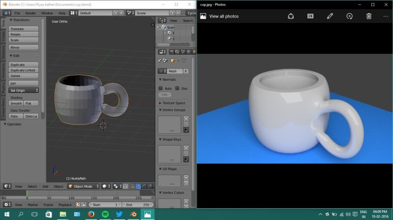
A cup created in Blender.
Solidworks
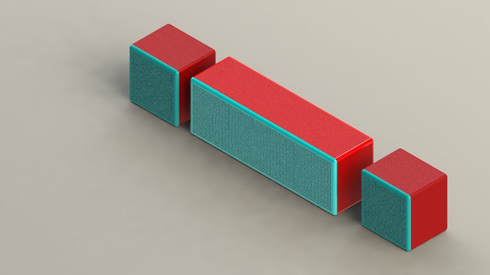
I have a intermediate knowledge on Solidworks,which I earned during my college days.Also as a hobby I worked on Solidworks several time.It is more convinient and easy to use.So I created a concept render of my project(Modular Wireless Speaker) on Solidworks.
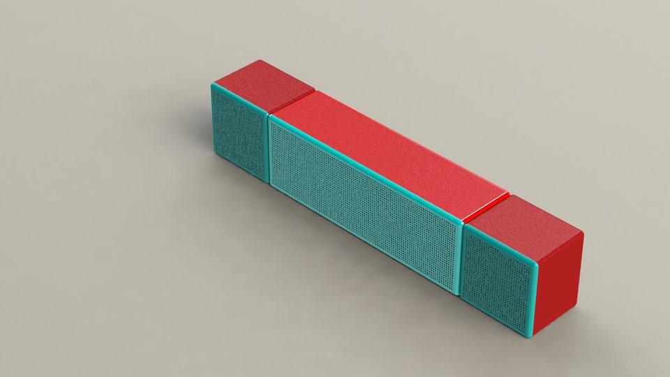
Concept-Assembled
Concept-Split
Working with solidworks is compartively easy.First draw the two dimensional view of the part using sketch.Then make it to three dimension using extrude feature.Several other useful tools are available solidworks for both sketch and feature.After making the parts you can join it together using assembly.For my concept I first created two parts,the sub and satellite.Then I joined it by assembly.After finalizing i used render tool to create the concept render above.I will upload a tutorial video of it in future.
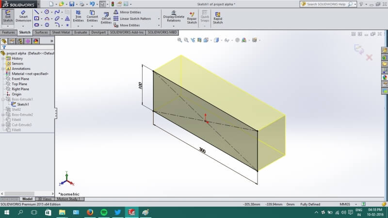
Working with solidworks
Design challenges:
The renderd image is a concept only there are things to be corrected.First is make it modular,the sub and satellites needs to be connected.Then there are several ports missing like charging port.The speaker and boards are nor included.I will keep working on it.
Files
- 2D drawing in psd(photoshop) format.
- The sub part in Solidworks format.
- The satellite part in Solidworks format.
- Assembled in Solidworks format.